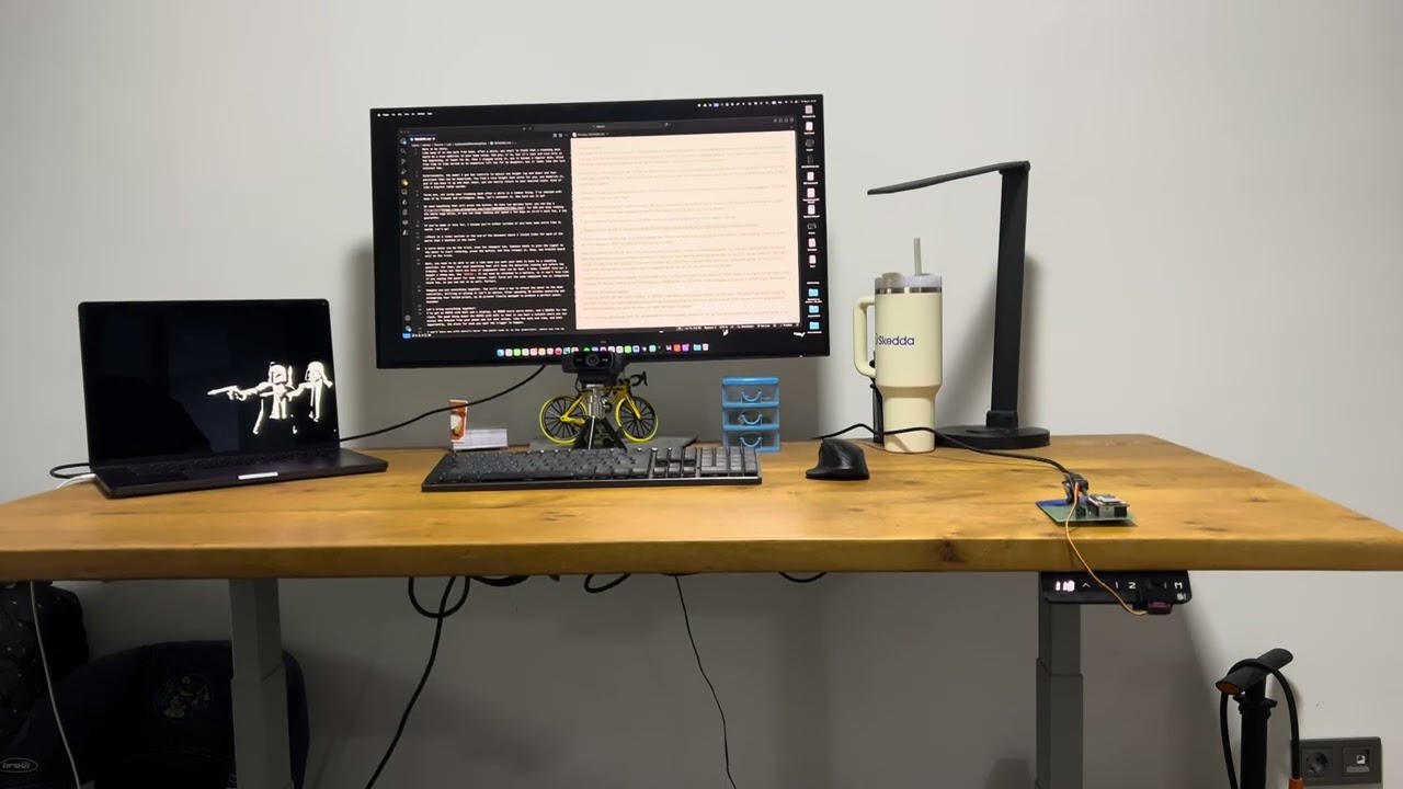
Here is my story. Like many of us who work from home, after a while, you start to think that a standing desk would be a nice addition to your home setup. And yes, it is, but it’s cool and nice only in the beginning, at least for me. Then I stopped using it, and it became a regular desk, which from time to time served as an expensive lift toy for my daughter… but it looks like she lost interest too.
Unfortunately, the model I got has controls to adjust the height (up and down) and four positions that can be memorized. You find a nice height that works for you, you memorize it, and if you move it up and down later, you can easily return to your desired state. Kind of like a digital radio system.
Turns out, not using your standing desk after a while is a common thing. I’ve checked with many of my friends and colleagues. Okay, let’s automate it. How hard can it be?
We need something that will press the button. We have two options here: you can buy a Fingerbot for $40 and skip reading the whole saga below, or you can keep reading and spend a few days on it—it's more fun, I can guarantee.
If you’ve made it this far, I assume you’re either curious or you have some extra time to spend. Let’s go!
There is a links section in the end of the document where I listed links for each of the parts that I mention in the text
A servo motor can do the trick, even the cheapest one. Someone needs to give the signal to the motor to start rotating, press the button, and then release it. Okay, any Arduino board will do the trick.
Next, you need to be able to set a time when you want your desk to move to a standing position. For that, you need something that will keep the date/time running and inform the Arduino. Turns out there are tons of components that can do that. I know, ChatGPT told me! I bought a cheap one, the DS3231. It can even be attached to a battery, so it won’t lose time if you unplug the power for some reason. Cool! Turns out the same component has an integrated alarm too, so you can set it as well. Perfect.
Imagine you put everything together. You still need a way to attach the motor to the desk controller, drilling or gluing it isn’t an option. After spending 30 minutes measuring and attempting four failed prints, my 3D printer finally managed to produce a perfect piece. Awesome!
Let’s bring everything together! I’ve got an ESP32 with WiFi and a display, an MG90S micro servo motor, and a DS3231 for the clock. The good thing about the ESP32 with WiFi is that it can host a network where you can access the Arduino from your phone and set some values, like the date and time, and most importantly, the alarm for when you want the trigger to happen.
I won’t bore you with details here; the whole code is in the repository, where you can go through it or even edit it yourself to tweak it. I’m sure you can make this better!
All the wiring details and technical descriptions are below if you want to go deeper. You can also see the 3D design and edit it to fit your desk or motor.
Now, I set the alarm on the DS3231 component via the Web interface and my desk is moving to standing position every day, 2minutes before the morning meeting. Yay!
Here is a video how it works in action (you may need to click on the picture to open the YouTube video):
An ESP32-based clock using a DS3231 RTC and SSD1306 OLED display.
It hosts a Wi‑Fi Access Point with a small web UI to:
- Set date/time on the RTC
- Configure a daily alarm
- Disable the alarm
- View current RTC time
When the alarm fires, the DS3231 triggers an interrupt on the ESP32, and the ESP32 drives a servo that “presses a button” (or any physical switch) via a simple press‑and‑return routine.
- Hardware timekeeping via DS3231 RTC (battery‑backed)
- OLED time display updated once per second
- Daily alarm using DS3231 Alarm1 interrupt pin
- Servo‑triggered action on alarm
- Wi‑Fi AP + Web UI for easy setup without needing a router
These pins are defined in the sketch:
| Module / Signal | ESP32 Pin | Notes |
|---|---|---|
| Servo signal | GPIO 18 | servoPin = 18 |
| RTC Alarm INT/SQW | GPIO 27 | ALARM_INT_PIN = 27, input pullup, falling edge ISR |
| I2C SDA | GPIO 21 | Wire.begin(21,22) |
| I2C SCL | GPIO 22 | Wire.begin(21,22) |
| OLED I2C addr | 0x3C | OLED_ADDR = 0x3C |
| Wi‑Fi AP SSID | ESP32-Clock |
password 12345678 |
RTC and OLED share the same I2C bus.

| DS3231 Pin | Connect to ESP32 | Notes |
|---|---|---|
| VCC | 3V3 | DS3231 modules are usually 3.3–5V tolerant; 3V3 is safest |
| GND | GND | common ground |
| SDA | GPIO 21 | I2C data |
| SCL | GPIO 22 | I2C clock |
| INT/SQW | GPIO 27 | alarm interrupt output |

| Servo Wire | Connect to ESP32 | Notes |
|---|---|---|
| Signal (usually yellow/orange) | GPIO 18 | PWM via LEDC |
| V+ (usually red) | 5V external recommended | ESP32 5V pin might work for micro servos but can brown out |
| GND (usually brown/black) | GND | must share ground with ESP32 |
Important: servo power spikes can reset the ESP32. Use a separate 5V supply if possible, and tie grounds together.
Legend:
==I2C bus line (shared)---single signal line+++power rail⏚ground rail
                    ┌──────────────────────────────┐
                    │             ESP32            │
                    │                              │
   3V3  +++─────────┤ 3V3                      GND ├────────⏚
                    │                              │
   SDA  ==──────────┤ GPIO21 (SDA)                 │
   SCL  ==──────────┤ GPIO22 (SCL)                 │
 Alarm ---──────────┤ GPIO27                       │
 Servo ---──────────┤ GPIO18 (PWM)                 │
                    └──────────────┬───────────────┘
                                   │
                   ┌───────────────┼
                   │               │
                   │               │
        I2C BUS ===│=== SDA/SCL ===│
                   │               │
                   ▼               ▼

      ┌─────────────────┐   ┌─────────────────┐
      │    DS3231 RTC   │   │      SERVO      │
      │                 │   │                 │
      │ VCC  +++────────┼───│ V+   +++ 5V EXT │
      │ GND  ⏚──────────│───│ GND  ⏚───────── ┼───⏚
      │ SDA  ==─────────┼───│ SIG  --- GPIO18 │
      │ SCL  ==─────────┼───└─────────────────┘
      │ INT  --- GPIO27 │
      └─────────────────┘
Power rails:
- 3V3 rail feeds RTC VCC and OLED VCC
- 5V external rail feeds Servo V+
- All grounds join at ESP32 GND
- RTC time is read once per second and drawn on the OLED.
- Daily alarm is set using DS3231 Alarm1 in “match hour/min/sec” mode.
- When alarm time matches, DS3231 pulls INT/SQW low, triggering ESP32 ISR.
- Main loop sees
alarmFiredFlagand:- clears RTC alarm flag
- runs
pressAndReturn()to actuate the servo
Servo routine (timings from code):
- Move “back” for
travelMs - Hold for
holdMs - Move “press” for
travelMs - Stop and settle
You can tune:
int pressUs  = 1150;
int backUs   = 1890;
int travelMs = 60;
int holdMs   = 15000;
int settleMs = 200;

Open in Arduino IDE (ESP32 core installed), select your board, then upload.
Here is my configuration for the board:

On your phone/laptop:
- SSID: ESP32-Clock
- Password: 12345678
Navigate to:
http://192.168.4.1/
You’ll see:
- Set Date & Time
- Daily Alarm
- Disable Alarm
- Status link

http://192.168.4.1/status returns plain text:
YYYY-MM-DD HH:MM:SS
- If your OLED doesn’t show anything, your module may be at 0x3D; change:
const uint8_t OLED_ADDR = 0x3D;
- DS3231 INT pin is open‑drain active‑low, so
INPUT_PULLUPis correct. - If the alarm fires immediately after setting:
- you likely left a stale alarm flag; the code clears alarms on set and on fire.
- Use a proper 5V servo supply for reliability.
- Add a “test servo” button to the UI
- Add multiple alarms (Alarm2 or software scheduling)
- Sync time from NTP when connected to the internet
- Show alarm status / next alarm time on OLED
- Draw PCB board where you can put the components directly, something like motherboard