This project is a desktop-level small robot tool. The inspiration for the appearance design is the EVE~ robot in WALL-E, which has the function of USB communication and display screen, and has 6 degrees of freedom (roll, pitch, neck, waist, etc.). A), use your own modified special servo to support joint angle return.


Loved the project? Please consider giving a Star ⭐️ to help it improve!
This project provides a complete set of development materials and corresponding SDK for secondary development. Please refer to the following for SDK usage instructions.
Video introduction: [Homemade] I made an active computer accessory! [Soft Core]_bilibili
**Note: Issues discuss topics related to project development, don't send meaningless messages in it, otherwise people who watch the warehouse will receive notification emails, which will cause trouble to others! ! ! Irrigation can be discussed in Discuss in the warehouse! **

22.4.5 update:
- Add a separate USB communication function test project and precompiled files in the
6.Tests\TestDisplayUSB\_Releaseddirectory; the method of use is to directly burn the hex file to the STM32F4, and then runSample.exedirectly on the computer. Normally, the screen will display the videos in the folder. - The source code and firmware of the above precompiled files are also provided in the folder, which is equivalent to a minimum test project, and you can view the code yourself for debugging.
- Note that before the 6 servos have not been successfully tested and verified, the debugging code should not use the function of the servos to send and receive commands, otherwise the bus will be blocked and the program will be stuck. Joint debugging.
For installation tutorials, please refer to:
The Simple Life of Digital Turtle Prenatal education-level tutorial for students: https://www.bilibili.com/video/BV1sY4y1Y7t6
Green Shadow Aguang The installation video of classmates: https://www.bilibili.com/video/BV1oY4y1v7oN
Updated on 22.4.17:
- Added voice recognition version of ElectronBot, thanks to jinsonli/ElectronBot-Voice for sharing, you can see this video for the demonstration effect: [I copied the computer accessories robot electronbot [ Voice version]] (https://www.bilibili.com/video/BV18a411v7JS)
- The servo debugging tool demonstrated in the video has been added to this repository
In the Hardware folder are the schematic diagrams and PCB files of all circuits used in ElectronBot. Source files in Altium Designer format and light drawing files in Gerber format are provided for direct processing by manufacturers.
There are a total of the following boards:
-
ElectronBot: The main control board of the head, including the main control MCUSTM32F405RGT6, the circular screen GC9A01, the USB-HS PHY chip USB3300, and the SD card.
-
SensorBoard: The sensor board in the stomach, including a gesture sensor, a USB-HUB chip, 5 I2C servo interfaces, an MPU6050 accelerometer & gyroscope, etc. (the USB camera is also connected to this board) .
-
BaseConnector: The USB Type-C socket on the base is connected to the SensorBoard through an 8-Pin FFC cable. Because the robot body needs to be rotated, a flexible cable is used.
-
ServoDrive: The circuit used to replace the servo drive board with the magic modified servo. It is connected to the SensorBoard and the head master through the I2C bus interface.
-
ServoDrive-DK: Same as above, but the contact interface of the PCB is replaced by a connector, which is convenient for debugging. After debugging, download the code to the above board (because the size is too small, the above board does not have a download port connector, So it is not convenient to debug, here is a separate DK version).
Firmware provides the firmware source code of all the above boards, mainly including the following two projects:
- ElectronBot-fw: The firmware code of the main control board of the head, used to drive the circular screen, implement the custom device of the USB-CDC protocol, and control the servo.
- ServoDrive-fw: ServoDrive board firmware, including servo potentiometer ADC sampling, I2C slave communication and protocol analysis, motor control PWM output, and PID closed-loop algorithm implementation.
- ServoDrive-fw-LL: It is also the firmware of the ServoDrive board. The difference from the above is that the LL library is used instead of the HAL library, so the Flash footprint will be smaller and can be put into a 16K MCU. Select the desired firmware depending on the situation.
The projects are all implemented based on STM32HAL, so the corresponding .ioc file is provided, which can be opened with STM32CubeMX by yourself to generate the corresponding keil or STM32IDE project file. When you can also compile and download with CLion like me, and turn CLion into an IDE for STM32, please refer to a tutorial I posted before: [Configuring CLion for STM32 Development [Elegant Embedded Development]](https ://zhuanlan.zhihu.com/p/145801160).
The software provides the Unity project source code of the host computer software ElectronStudio demonstrated in the video, as well as the SDK library and SDK source files. The hierarchical relationship of the library from bottom to top is:
ElectronBotSDK-LowLevel -> ElectronBotSDK-Player -> ElectronBotSDK-UnityBridge -> Electron-Studio
See below for how to use the SDK.
In addition, the folder also contains BotDriver, which is the USB driver file that ElectronBot needs to install to connect to the computer. The installation method is to right-click in the device manager to update the driver, and then select the custom directory to navigate to this folder to install.
During the installation process, you need to disable the mandatory driver signature of Windows (there is no money to buy a signature for M$). The method of disabling is different according to your operating system version. You can check it on Baidu.
The folder contains the structural design drawings of ElectronBot. The .step general format can be opened and edited in all software; at the same time, in order to satisfy some students who want the original project in Fusion360, I also shared the .f3d format source file , the source file contains the complete editing modeling timeline.
Shared Connection: https://a360.co/3t6CUMS
This directory also contains the emoji animations designed by students oooooohmygosh demonstrated in the video. Each emoji animation contains three segments: Enter-loop -Exit, entry and exit can be seamlessly connected with other animations, so it is convenient to call these emoticons with code to achieve many effects.
The emoji file needs to be modified to English name and path before use.
I also uploaded the storage box mentioned at the end of the video, which can be printed with FDM and filled with 5%.

Relevant reference documents, including the chip's Datasheet, etc.
There is also a _LargeFiles folder in this directory, which is some libraries (such as OpenCV) that the software process project depends on. Because the DLL is larger than 100MB, GitHub needs to open LFS to submit, and I don't want to open LFS, so I take it out and compress it separately In order to submit to the warehouse, you need to put these libraries in the corresponding project directory when compiling the project. For the specific path, see _path.txt.
The hardware of the robot is divided into structure and circuit.
In terms of structural design, you can study 3D drawings. The points worth noting are as follows:
**How the main components are processed? **
-
I used 3D printing, because it contains precision parts such as gears, the accuracy of traditional FDM printing may not be ideal, light curing is possible, but the support problem may cause the surface of the printer to be uneven, and the strength of LCD light-cured parts Not enough. Therefore, it is recommended to use HP nylon printing, you can go to Jia Li Chuang (3D monkey) to print, the price of these parts should add up to about 200-300 yuan.
-
Several bearings and some special screws are also used. The bearing model is
6x10x3mmfor the shoulder joint, and the model for the waist bearing is25x32x4mm. The special screw is the push rod of the shoulder roll degree of freedom, and theM2x25mmhalf-thread screw is used. -
The arm push rod also uses a small block, this block does not need to be printed, just cut a small section with a piece of rubber wire (there is a demonstration in the video), this block needs to be fixed with the screw of the push rod. Yes, 502 bonding can be used.
**The driving principle of the arm? **
-
In fact, it is demonstrated in the video. I designed a relatively ingenious driving method. The pitch direction movement is well understood as gear transmission. The roll direction uses a T-shaped push rod as follows:

-
The push rod is restricted by the cap of the M2 screw and a stopper. When the yellow component rotates, it drives the push rod to move left and right, and the other end of the push rod is restricted by a guide groove in the arm assembly to transmit the power. To the rotating shaft, the torque of this scheme can be transmitted in both directions


How the clear glass for the face is made
*tb search for Table Mengzi, I used the 31.5mm diameter.

**Installation order? **
You can refer to the installation video of this [Green Shadow Aguang] (https://space.bilibili.com/25228512): https://www.bilibili.com/video/BV1oY4y1v7oN
- It is also worth noting that during the installation process, because the volume of the fuselage is too limited, some of the mounting brackets of several servos need to be cut short, otherwise they cannot be plugged. Can be fixed with hot melt glue.
- In addition, the push rod of the arm can be slightly polished and greased to make it push more smoothly.
There is nothing to analyze the circuit, just look at the schematic diagram.
It is worth mentioning that the topology of the USB-HUB is as follows:

**About chip selection? **
- Master STM32F4, this is irreplaceable, because models below F4 do not support USB-HS external PHY.
- The STM32F0 driven by the steering gear can be replaced, and it is recommended that capable students replace it, because the STM32F042P6 chip used in my project is more expensive (bought a piece of more than ten yuan), and the performance requirements of the steering gear driver are not so much for the chip High, it can be replaced by 8-bit MCU such as STM8, so you can refer to my firmware source code to find a replacement MCU to improve the solution.
- The MCU that replaces the STM32F0 needs to support the following features: with an ADC sampling, with two PWM outputs, with an I2C interface, the Flash and SRAM size needs to be 32K and 4K or larger according to my code (My firmware uses HAL library and C++ Features, if you can be based on the LL library or don't use C++, the requirements should be half as small).
**About the burning method? **
- Use debuggers such as JLink and STLink for programming. Note that only three programming contacts are left on the driver board due to the size limit. You need to use the
SH1.0connector contacts for programming.
**About the modification of the steering gear? **
-
The usual RC-Servo uses potentiometers to measure the absolute angle, so I also use the ADC to read the voltage value of the potentiometer in the driver board and convert it into angle feedback, and the driver chip uses the smallest package I found. A chip
FM116B. When you modify the steering gear, pay attention to distinguish the direction of the two wires of the motor. If the debugging finds that the motor is not closed-loop, you may need to exchange the wiring sequence. -
In addition, the transformation of the small 3g servo needs to disassemble and remove the cover (the space is too small to add the cover driver and can't be plugged in), and then the servo with the rear cover removed needs to be replaced with M1x10mm screws for fixing, otherwise it will fall apart. of.
In fact, the ideal situation is to find a steering gear manufacturer to customize a mini steering gear like this, but because I am doing small batches by myself, I will definitely not accept orders. If you have channels, you can try it.
**About camera selection? **
-
I use this one: https://item.taobao.com/item.htm?id=567717780577

-
Of course, you can replace other USB cameras (black and white, high frame rate) according to your needs, as long as it can be plugged in, the camera is directly disconnected and welded on the SensorBoard.
It is worth noting that the 1-to-4 port of the USB-HUB chip I used currently uses three ports, and the remaining one can actually integrate a USB microphone, so that ElectronBot can also be used as a computer microphone used.

The details and process descriptions of the firmware code are relatively cumbersome. I will add them later. In short, you can compile and download directly based on the method mentioned above, and then slowly study the source code.
If the source code of STM32F4 regenerates the project through
.ioc, remember to back up several files related to USB in advance, and then replace the original file after generating the code, because CubeMX will overwrite the generation and modify the relevant code ( I actually use Git's file version rollback operation).
The modified steering gear communicates with the control board through the I2C interface. The control board of the STM32F4 is the master and the steering gear is the slave. The communication process is always initiated by the host. The host first issues commands such as location and parameters, and then retrieves the relevant data immediately to complete a round-trip communication.
Each servo acts as a slave to receive commands from two addresses: ** own ID number , and ** broadcast number 0. Broadcast is used as a wildcard address when no address is set for the servo (for example, if you have just programmed the servo firmware, at this time the servo's Flash does not store its own ID, and can only communicate through address 0) .
**It is worth noting that the power-on of the servo and the host needs to be in order. Be sure to let the slave machine initialize and start monitoring data, and then let the host send commands! **
If the slave does not respond when the host sends a command, or if multiple servos with the same address respond at the same time, it may cause a communication error, so the above sequence needs to be guaranteed.
Since the host and the servos are powered on at the same time on the hardware, there is a 2S delay code in the host's firmware code (in fact, it doesn't take that long), which is to wait for the servos to be powered on and the initialization is completed before starting the communication.
When debugging, debug one servo and one servo, and comment out the communication codes of other unconnected servos, otherwise it will also cause polling to wait for timeout.
Regarding the command meaning of the steering gear, I would like to thank leazer for the table organized by the students in Issues:
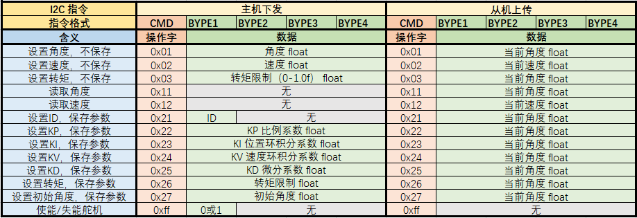
Instructions may be updated in the future.
The SDK architecture design is shown in the figure:

For the specific usage method, please refer to the sample.cpp given in the SDK project. I compiled it with the CLion+MSVC toolchain. You can also copy the source code to your own Visual Studio project for compilation.
The DLL files generated by the ElectronBotSDK-UnityBridge project need to be copied to the Unity\ElectronBot-Studio\Assets\Plugins directory to connect the local C++ code and the C# environment in Unity.
**By the way, note that the current selection of picture and video files in ElectronStudio does not support Chinese paths! **
For the specific implementation details of the SDK, you can read the source code, and I will update the description later when I have time.
Some questions have already been answered in Issues, please read open/closed Issues before asking questions.
Thanks to the following items:
opencv/opencv: Open Source Computer Vision Library (github.com)